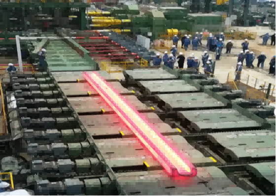
A mill shaft is a rotating mechanical component that transmits torque and power within a milling machine or mill drive system. A spindle, on the other hand, is a precision-engineered rotating assembly designed to support and drive a cutting tool, workpiece, or other working component. While the terms can overlap — a machine-tool spindle contains a shaft — the spindle’s performance also depends on its bearings, interfaces, alignment, stiffness, and thermal stability, as discussed in Machine Tool Spindle Units by Abele, Altintas and Brecher in CIRP Annals—Manufacturing Technology (2010).
Therefore, the practical distinction is not simply the component’s shape or size. Rather, it is the component's primary function: mill shafts are usually specified in terms of torque transmission, load capacity, and mechanical reliability, whereas spindles are specified in terms of rotational accuracy, stiffness, speed capability, and the quality of the machining or other operation they enable. As manufacturers sometimes use the terms differently, the machine type and the component’s position in the drive system should always be considered.
What Is a Mill Shaft?
A mill shaft is a rotating component that transmits mechanical power, torque, or rotational motion within milling equipment. Depending on the machine, it may connect a motor or gearbox to a working mechanism, transmit torque to a roll or cutter, support a rotating element, or form part of a larger drive train. The exact design of a mill shaft varies significantly between applications: for example, a shaft used in a metal rolling mill may have very different dimensions, load requirements and connection features to a shaft used in a machining centre.
In industrial mills, the shaft must withstand torsional stress, bending loads, cyclic loading and, sometimes, impact or shock loads. Engineers select the diameter, material, heat treatment, surface finish and connection geometry of the shaft according to the transmitted torque, operating speed, support arrangement and expected service life. Keyways, splines, shoulders and bearing journals may be incorporated to connect gears, couplings, rolls or other components. Stress concentrations around these features require particular attention because fatigue cracks often initiate where geometry changes abruptly.
A mill shaft does not necessarily provide the precision tool interface associated with a machine-tool spindle. In many installations, its main responsibility is to reliably deliver power while maintaining the alignment of connected components. While dimensional accuracy remains important, particularly at bearing seats and coupling interfaces, the required tolerances depend on the machine’s function rather than the generic term 'mill shaft'.
For procurement and maintenance teams, identifying the shaft’s actual operating role is more useful than relying on its name alone. For example, a shaft in a rolling mill drive, a milling machine transmission and a grinding system may all transmit torque, yet their requirements for torsional stiffness, bending resistance, wear resistance and precision can differ substantially.
What Is a Spindle?
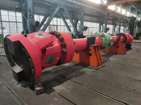
A spindle is a rotating component that holds, supports and drives a tool, workpiece or other working element. In machine tools, the spindle is central to the machining process because its behaviour when rotating directly influences cutting stability, dimensional accuracy, surface finish and productivity. Spindles are used in milling machines, lathes, drilling machines, grinding machines and machining centres, although their configuration changes according to the operation being performed.
Unlike a generic power-transmission shaft, a machine-tool spindle is usually designed as part of a precision system. This system may include the spindle shaft, precision bearings, a tool or workholding interface, a drive mechanism, and components for lubrication, sealing, and cooling. Some designs use a belt or gearbox connected to an external motor, while others integrate the motor directly into the spindle assembly. These choices affect torque delivery, maximum speed, heat generation, maintenance requirements, and overall machine performance.
Spindle accuracy depends on several interacting factors. Bearing arrangement and preload influence stiffness and rotational runout, while shaft geometry, bearing-seat accuracy, assembly quality, balance, and thermal behaviour affect how consistently the tool or workpiece rotates. A spindle that runs at high speed but experiences excessive vibration or thermal growth may produce poor surface finishes or parts that are outside the required tolerances. Consequently, research on spindle-bearing systems examines static stiffness, dynamic response, heat generation, and vibration as interconnected design concerns, rather than treating the shaft as an isolated part.
The term spindle is not limited to machine tools. It can describe rotating assemblies in other equipment, including textile machinery and specialized industrial systems. However, when comparing a mill shaft with a spindle in machining, the key distinction is that the spindle is designed around the requirements of the working interface, not merely the transmission of rotational power.
Mill Shaft vs. Spindle: Key Differences
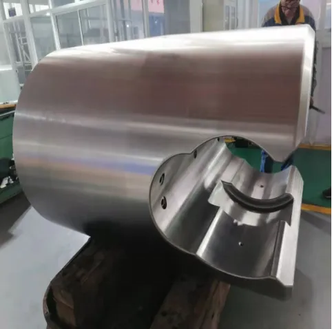
Although both components can rotate and transmit torque, they are generally designed to meet different functional priorities. A mill shaft may be one element within a machine’s power-transmission system, whereas a spindle often serves as the precision rotating interface closest to the tool or workpiece. The comparison below applies to common industrial and machine-tool usage; the exact specifications depend on the equipment design.
| Comparison factor | Mill shaft | Spindle |
| Primary function | Transmits torque and rotational power within a mill or drive system | Holds and rotates a tool, workpiece, or working component |
| Design priority | Torque capacity, load resistance, fatigue life, and reliable power transmission | Rotational accuracy, stiffness, dynamic stability, and operating speed |
| Typical configuration | May be a standalone shaft or part of a drive train | Often an integrated assembly containing a shaft, bearings, and working interface |
| Accuracy requirements | Depends on bearing seats, couplings, alignment, and machine function | Often stringent at the bearing seats, spindle nose, taper, or chuck interface |
| Load conditions | Frequently designed for substantial torsional and bending loads | Must withstand process loads while maintaining accurate rotation |
| Speed requirements | Set by the mill process and transmission system | Matched to the tool or workpiece, cutting conditions, and machine capability |
| Common failure concerns | Fatigue, torsional overload, wear, misalignment, and connection damage | Bearing damage, excessive runout, vibration, thermal growth, and tool-interface wear |
| Typical evaluation criteria | Torque, shaft strength, fatigue life, material, and connection geometry | Runout, stiffness, speed range, power, torque curve, thermal stability, and interface accuracy |
The table highlights a useful distinction, but it should not be interpreted as an absolute separation. A mill shaft may require high precision, and a spindle must also transmit torque and withstand mechanical loads. In fact, the spindle shaft is itself a shaft; the word spindle identifies its role within a more demanding rotating system. Timken’s Engineering Manual explicitly notes that machine-tool terminology commonly refers to the shaft as the spindle, illustrating why the terms sometimes overlap.
How Do Mill Shaft and Spindle Designs Differ?
The most significant engineering distinction is how a component's function influences its geometry, material selection, manufacturing tolerances, and validation requirements. While a mill shaft is typically sized according to the torque and external forces it must withstand, a precision spindle must also maintain the required position and orientation of the tool or workpiece when speeds, temperatures, and cutting loads change. While both require sound mechanical design, the acceptable compromises differ.
- Material selection and mechanical strength
Mill shafts are typically made of carbon or alloy steel, and the grade of material is chosen based on factors such as transmitted torque, bending stress, fatigue resistance, wear, and environmental conditions. Depending on the application, heat treatment, surface hardening, or other surface treatments may be used to improve fatigue performance and resistance to wear at bearing journals, splines, and coupling interfaces. For heavy-duty equipment, the choice of material must also take into account shock loads and the consequences of unexpected overloads.
Spindle shafts may use high-strength alloy steels, but the choice of material is closely connected to rotational accuracy, stiffness, balance and thermal behaviour. A spindle operating at high speed must be able to withstand centrifugal forces and maintain stable geometry as heat builds up in its bearings, motor and surrounding structure. Research published in CIRP Annals on thermo-mechanical spindle modelling demonstrates the importance of considering temperature distribution and thermal expansion when predicting spindle performance.
- Manufacturing accuracy and surface finish
The most critical dimensions for a mill shaft commonly include the shaft's diameter, the fit of the bearing seat, the geometry of the keyway or spline, concentricity, and the alignment of connected components. These features determine how effectively the shaft transfers power and how well it operates within the supporting bearings and drive system. According to the component’s load and service requirements, machining, heat treatment, grinding, and non-destructive inspection may be required.
Precision spindles generally require tighter control over the geometry of their bearing seats, spindle nose, tool-holder taper, and other functional interfaces. Small errors in these areas can affect runout, tool positioning, vibration, and the quality of the finished part. Therefore, the required accuracy should be defined by measurable specifications, such as radial and axial runout at a stated measurement location, rather than simply describing the component as “high precision”. Bearing mounting and fitting practices are particularly important because bearing quality alone cannot compensate for poorly manufactured supporting surfaces.
- Speed, stiffness, and thermal stability
Operating speed influences both components, but it is often the defining performance variable for a machine tool spindle. At high rotational speeds, factors such as bearing friction, motor losses, imbalance, and cutting forces can contribute to vibration and heat generation. Excessive thermal growth can cause the tool tip to shift relative to the workpiece, even if the spindle's initial geometric accuracy is satisfactory. Spindle design therefore involves balancing speed capability, stiffness, bearing preload, lubrication, cooling and service life.
For a mill shaft, torsional strength and bending stiffness may be the dominant considerations, particularly when transmitting high torque through a gearbox, coupling, roll or other driven mechanism. However, 'heavy-duty' does not mean that precision is unimportant; misalignment, shaft deflection, or imbalance can accelerate bearing wear and cause vibration throughout the machine. Design priorities must be established based on actual operating conditions rather than assumed from the component name.
Mill Shaft vs. Spindle: Which Specifications Matter Most?
When evaluating a replacement component or comparing suppliers, buyers should translate the machine’s operating requirements into verifiable technical specifications. A drawing that provides only overall length and nominal diameter is rarely sufficient for a critical rotating component, especially when it must fit existing bearings, couplings, or tool interfaces.
| Specification | Mill shaft: what to check | Spindle: what to check |
| Torque and power | Rated and peak torque, transmitted power, overload conditions | Torque and power curves across the required speed range |
| Rotational speed | Normal speed, maximum speed, and transmission ratio | Continuous and maximum rated speed under specified conditions |
| Geometry | Diameter, length, shoulders, keyways, splines, and coupling dimensions | Bearing-seat geometry, spindle nose, taper, bore, and tool interface |
| Mechanical stiffness | Torsional and bending deflection under working loads | Static and dynamic stiffness at the tool or workpiece interface |
| Accuracy | Runout and alignment requirements at critical shaft locations | Radial and axial runout, taper accuracy, and interface repeatability |
| Materials and treatment | Strength, fatigue resistance, hardness, and wear requirements | Strength, balance stability, wear resistance, and thermal behavior |
| Supporting components | Couplings, gears, rolls, bearings, and seals | Bearings, tool holder, drawbar, drive, lubrication, and cooling |
| Inspection and testing | Dimensional inspection, material verification, and applicable fatigue or nondestructive tests | Runout, balancing, vibration, temperature rise, and performance testing as specified |
Not every application needs every test in the table. A replacement mill shaft may require material certification and dimensional inspection, while a high-speed machining spindle may additionally need documented runout, balance, vibration, and thermal performance. Acceptance criteria should be agreed upon before manufacturing and linked to the machine’s actual duty cycle.
How to Choose Between a Mill Shaft and a Spindle Supplier?
The correct purchasing decision starts with the machine’s functional requirements, not the product label used in a catalog. If the component primarily transfers torque between a drive and a working mechanism, a mill shaft may be the appropriate description. If it directly supports and drives a cutting tool or workpiece and must maintain precise rotation, a spindle or spindle assembly is generally the more relevant category.
Before requesting a quotation, follow these steps:
- Define the application. Identify the machine type, component position, working process, and whether the part directly interfaces with a tool, workpiece, roll, or transmission element.
- Provide operating data. Specify continuous and peak torque, speed range, radial and axial loads, duty cycle, temperature, lubrication, and environmental conditions.
- Supply the interface dimensions. Include drawings, tolerances, bearing fits, shoulders, splines, keyways, taper dimensions, and any required assembly clearances.
- Agree on performance criteria. For shafts, define strength, deflection, fatigue, and dimensional requirements. For spindles, include runout, stiffness, balance, vibration, thermal stability, and the required tool or workholding interface where applicable.
- Verify quality documentation. Confirm material certificates, heat-treatment records, inspection reports, and performance test results relevant to the component’s criticality.
A capable supplier should be able to explain how the proposed design meets the operating requirements and identify any missing information before production begins. For spindle assemblies in particular, evaluating only the shaft material or maximum RPM is insufficient; the bearing arrangement, drive system, tool interface, cooling method, and operating conditions all influence the result.
Frequently Asked Questions About Mill Shafts and Spindles
- Is a spindle the same as a shaft?
Not exactly. A spindle is a type of rotating shaft or a shaft-based assembly designed for a particular working function, often involving precision rotation and tool or workpiece support.
- What is the main function of a mill shaft?
A mill shaft primarily transmits torque and rotational power through milling or other industrial equipment. Its design depends on the connected components, operating loads, speed, and service conditions.
- Can a mill shaft be used as a spindle?
Only if it satisfies the spindle’s dimensional, stiffness, speed, bearing, and accuracy requirements. A shaft that transmits sufficient torque may still be unsuitable for precision machining because of excessive runout, deflection, or thermal instability.
- Which is more precise, a mill shaft or a spindle?
A machine-tool spindle is generally designed to meet more demanding rotational-accuracy requirements at its working interface. However, some industrial mill shafts also require tight tolerances, so the actual specification matters more than the name.
- What causes a spindle to fail?
Common causes include bearing damage, inadequate lubrication, contamination, imbalance, excessive loading, poor tool-holder installation, and overheating. Incorrect bearing preload or thermal growth can also reduce stiffness and machining accuracy.
- How do I select the correct mill shaft or spindle replacement?
Start with the original drawing, machine model, interface dimensions, operating speed, load requirements, and applicable accuracy tolerances. Confirm compatibility with the bearings and connected components, and request inspection or performance records appropriate to the application.
Conclusion
The difference between a mill shaft and a spindle is primarily functional rather than geometric. While a mill shaft is designed to transmit power and withstand mechanical loads, a precision machine-tool spindle must deliver power without compromising rotational accuracy, stiffness, stability or the quality of the machining process.
The most reliable way for engineers, maintenance teams and industrial buyers to distinguish between the two is to examine the component’s position in the machine, its connection interfaces and its required operating performance. Selecting the right component and specifying measurable acceptance criteria helps to reduce premature failures, improve machine reliability, and maintain production quality.