The three main materials charged into a blast furnace are iron-bearing substances, coke, and fluxes. Iron-bearing materials, such as sinter, pellets, and lump ore, provide iron; coke supplies heat, carbon, and reducing gases, as well as forming the permeable skeleton of the burden; and fluxes, such as limestone and dolomite, control the chemistry of the slag and remove impurities from the gangue. This basic classification is consistent with Modern Blast Furnace Ironmaking: An Introduction, which discusses the ferrous burden, coke, burden calculation and burden distribution separately as fundamental parts of blast furnace operation.
For modern ironmaking, it is important to recognise that the materials charged and the manner in which they are charged are inseparable. Blast furnace charging equipment controls the weighing, sequencing, conveying, buffering and distribution of burden materials, while the final charging pattern determines the accumulation of ore and coke across the furnace throat. Studies of bell-less top systems demonstrate that burden distribution influences gas flow, permeability, reduction behaviour and furnace productivity. Furthermore, recent DEM research has revealed that particle size, segregation, degradation and chute movement can significantly alter the material profile formed during charging.
What Does Charging a Blast Furnace Mean?
Blast furnace charging involves the controlled introduction of solid raw materials into the furnace from above. These materials are usually prepared in a stockhouse, screened if necessary, weighed according to the burden calculation, and transferred towards the top of the furnace. They are then discharged through the charging system according to a defined operating programme. The objective is not merely to fill the furnace, but rather to create a consistent burden structure that enables the solids to descend smoothly while the reducing gas flows upwards through the bed at an appropriate pressure and with an even distribution.
A blast furnace is essentially a counter-current gas-solid reactor. Ferrous materials descend towards the lower furnace, which is at a high temperature, while gas generated near the tuyeres moves upwards through the burden. The coke and ferrous burden therefore form a layered or partially structured granular bed, the voidage, permeability, particle size distribution and radial composition of which all influence the path of the gas. Technical literature on blast furnace charging recognises burden distribution as a significant mechanism through which operators can influence gas distribution and utilisation.
This is why blast furnace charging equipment is an important process system rather than merely a material handling installation. A charging system must maintain accurate mass flow while minimising unnecessary degradation and segregation, and at the same time give operators sufficient control over where each material enters the furnace. In modern installations, this typically involves combining stockhouse equipment with a skip or conveyor system and a bell-less top charging arrangement.
The Three Main Components of a Blast Furnace Charge
The three principal components can be summarized as ferrous burden, coke, and flux. They perform different functions, and their properties must be considered together because changing one component can alter the operating requirements for the others.
| Main charge component | Typical materials | Primary function in the furnace | Important charging considerations |
| Iron-bearing materials | Sinter, pellets, lump ore | Supply iron units for hot-metal production | Size distribution, reducibility, strength, reducibility under load, fines content |
| Coke | Blast furnace coke | Provides heat, carbon, reducing gas generation, and permeability | CSR/CRI, strength, size distribution, degradation, layer thickness |
| Fluxes | Limestone, dolomite and other flux-bearing materials | Adjust slag chemistry and combine with gangue and impurities | Chemical composition, particle size, basicity requirement, distribution |
The exact burden recipe is not universal. It depends on ore quality, coke quality, desired hot-metal chemistry, slag requirements, furnace volume, productivity targets, auxiliary fuel injection, and the operating strategy of the particular plant. For this reason, the three components should be regarded as functional categories rather than fixed percentages. Modern Blast Furnace Ironmaking specifically treats the ferrous burden, coke quality, burden calculation, and burden distribution as interconnected subjects rather than isolated material choices.
-
Iron-Bearing Materials
Iron-bearing materials are the principal source of iron in the charge. The most common forms are sinter, pellets, and lump ore, although the combination varies between plants depending on raw-material availability, furnace design, and process economics.
Sinter is produced by agglomerating a prepared mixture of fine iron ores and other materials through a high-temperature sintering process. Pellets are manufactured by pelletizing fine iron-bearing concentrates and subsequently hardening the green pellets through thermal treatment. Lump ore, where suitable resources are available, can be charged directly after appropriate preparation and screening. These materials differ substantially in size, density, shape, reducibility, mechanical strength, and degradation behavior, so they do not necessarily travel through the charging system in the same way.
This physical difference becomes particularly important at the furnace top. Larger and smaller particles can segregate as material moves through bins, hoppers, chutes, and onto the burden surface. A 2025 GPU-DEM study of a full bell-less blast furnace charging system found that particle properties and size distributions strongly affect flow behavior and segregation, while different burden materials experienced different levels of degradation during charging.
Consequently, an effective charging system needs to be designed around the actual ferrous burden rather than treating ore, sinter, and pellets as interchangeable bulk solids.
-
Coke
Coke is the second major component and performs several functions simultaneously. It is a fuel, a source of carbon, a participant in the generation of reducing gas, and an essential structural material that helps maintain permeability as the burden descends through the furnace.
The structural role of coke is particularly important because the blast furnace cannot operate efficiently if the burden becomes excessively compacted. Coke particles create relatively large voids through which reducing gas can rise. At high temperatures, coke also has to retain sufficient mechanical strength to support the burden and resist degradation.
Coke is therefore evaluated using properties such as size distribution, mechanical strength, reactivity, and post-reaction strength. Its behavior during charging also matters. If coke breaks excessively or becomes unevenly distributed, the resulting change in local voidage can alter gas flow and the radial ore-to-coke relationship.
Research on bell-less top charging has specifically examined coke collapse, because movement of the coke layer during subsequent ore charging can change the final radial distribution. Numerical studies have shown that charging strategies and central coke charging can influence the ore-to-coke distribution at the furnace throat.
-
Fluxes
Fluxes form the third major category. Limestone and dolomite are common examples, although the precise materials and additions depend on the raw-material chemistry and the required slag composition.
Their principal function is to help establish the desired slag chemistry. During the high-temperature reactions inside the furnace, flux-derived oxides interact with gangue and other components from the burden to form slag. The resulting slag must have suitable characteristics for separation from hot metal and for stable furnace operation.
Flux requirements are closely connected with the chemistry of the ferrous burden. A change in the silica, alumina, calcium oxide, magnesium oxide, or other relevant constituents entering with the ore can change the amount and composition of flux required. Consequently, a charging system must accommodate the burden calculation generated by the process rather than applying an inflexible material sequence.
Fluxes also demonstrate why accurate weighing is important. Even though the mass of flux may be considerably lower than the total ferrous burden in some operating recipes, an error repeated over many charging cycles can accumulate into a meaningful chemical imbalance.
Why the Charging Method Matters as Much as the Material?
Understanding the three charge components does not explain why blast furnace charging systems are engineered with such precision. The furnace does not experience an even mixture of all the raw materials, but rather a three-dimensional distribution of particles across the throat and along the descending burden.
When coke and ferrous materials are charged in controlled layers, their relative position affects the local voidage, and thus the resistance encountered by ascending gas. Regions containing more coke generally have different permeability characteristics than regions dominated by finer ferrous material. Consequently, operators can use charging patterns to influence the radial gas-flow profile.
This relationship is well established in blast furnace research. A review of burden distribution models describes the bell-less top with parallel or serial hoppers as the primary type of charging equipment used in modern blast furnaces due to its flexibility in controlling burden distribution. The material passes through components such as the hopper, throttle valve, feeding pipe, and rotating chute before reaching the burden surface.
The practical consequence is clear: a charging system should be evaluated not only by its conveying capacity, but also by its ability to consistently reproduce the required burden distribution.
What Is Blast Furnace Charging Equipment?
Blast furnace charging equipment comprises an integrated group of machines and mechanisms that are responsible for moving, measuring, storing, and distributing burden materials from the stockhouse to the furnace throat.
A typical system may include raw material bins, vibrating feeders, weighing equipment, conveyors, screening units, transfer points, skip hoists, top conveyors, receiving hoppers, sealing equipment, throttle valves, feeding chutes and rotating chutes, as well as associated hydraulic, electrical, instrumentation and control systems. The exact configuration depends on the furnace's capacity and the plant's layout.
Two broad charging concepts have historically been important at the furnace top: bell-type charging and bell-less top charging. Modern large blast furnaces commonly use bell-less systems because the rotating chute provides greater flexibility in controlling the radial distribution of the burden. A review of the literature on burden distribution identifies bell-less top systems as the main charging equipment used on contemporary blast furnaces.
Therefore, the equipment has to satisfy several requirements simultaneously, such as reliable material flow, accurate batching, pressure sealing, controlled discharge, mechanical durability, and sufficient distribution flexibility. Even if a system meets the first requirement, it may still produce poor furnace performance if it cannot reproduce the required charging pattern.
How Does a Bell-Less Top Charging System Work?
In a typical bell-less top arrangement, the prepared burden is transferred into one or more top hoppers. The hopper then temporarily stores the material, maintaining the necessary pressure-sealing conditions between the furnace interior and the upstream conveying system.
When the charging sequence calls for a particular material, a controlled discharge mechanism enables the burden to move through the feeding passage towards the rotating chute. The chute can rotate around the furnace axis and adjust its inclination, enabling the material to be deposited at various radial positions.
This provides substantially more flexibility than a fixed discharge point. Rather than repeatedly dropping material in approximately the same location, the control system can create a sequence of charging positions designed to produce the desired stockline and radial ore-to-coke distribution.
The principle is simple, but the particle flow is not. The material accelerates, collides, rolls, slides, and segregates as it passes through the system. A 2025 study using GPU-accelerated discrete element modelling found that particle properties, energy dissipation, segregation and degradation varied at different stages of a full bell-less charging system.
This means that, for equipment manufacturers and furnace operators, mechanical design and process control must be considered together. The final burden profile is affected by the chute angle, rotation speed, hopper geometry, discharge characteristics, and material properties.
The Role of Burden Distribution in Furnace Performance
The way in which different materials are positioned across the furnace cross-section is determined by burden distribution. This has an impact on local permeability, gas velocity, reduction conditions, heat transfer, and the development of the cohesive zone.
One of the most important variables is the radial distribution of the ore-to-coke ratio. If this ratio becomes too high in one region, gas flow may be restricted there. Conversely, if gas is forced into a region with lower resistance, the resulting distribution may become increasingly uneven. This can reduce the effectiveness of gas-solid contact and create undesirable operating conditions.
Therefore, the objective is not simply to make the burden symmetrical in a geometric sense. A furnace may require a deliberately designed distribution profile to achieve the desired gas flow pattern. The appropriate profile depends on the geometry of the furnace, the raw materials used, the operating conditions, and the furnace control strategy.
This is also why stockline measurements and burden-profile monitoring are useful. Research using multi-radar measurements has demonstrated that burden profiles can be estimated in real time and used to calculate the radial distribution of ore to coke.
Modern blast furnace operation increasingly combines these measurements with mathematical models, process data and numerical simulations, rather than relying solely on predetermined charging tables.
Particle Size and Segregation: An Often-Overlooked Charging Issue
Even if they have an identical chemical composition, two batches can produce different charging behaviour if their particle size distributions are different. This is particularly relevant because blast furnace burden is not composed of uniform particles.
During transportation and discharge, larger particles tend to behave differently from smaller particles. Differences in density, shape, friction, and momentum can cause segregation inside hoppers and on the burden surface. Such segregation can change local permeability and therefore affect gas flow, even though the average chemical composition of the charge remains unchanged.
Recent research has highlighted this problem. One study of sinter charging in a bell-less top system from 2025 found pronounced particle segregation at the upper and lower surfaces of the sinter layer. Another recent study reported that, under certain flow conditions, larger particles can accumulate towards the periphery and upper portions of the charged burden.
These findings have practical implications for blast furnace charging equipment. Hopper geometry, chute design, discharge velocity, transfer-point configuration, and material residence time should be evaluated in relation to the actual particle size distribution. Simply increasing conveying capacity does not necessarily improve charging quality.
Key Equipment Considerations When Selecting a Charging System
For a new blast furnace or a charging-system upgrade, equipment selection should begin with the required process conditions rather than with the nameplate capacity alone. The system needs to handle the maximum and minimum burden rates, material density variations, particle-size range, charging sequence, required radial distribution, furnace pressure, maintenance conditions, and available plant space.
| Equipment factor | Why it matters | Typical engineering focus |
| Weighing accuracy | Determines whether the actual burden matches the calculated recipe | Load cells, calibration, batching logic |
| Hopper capacity | Provides sufficient buffer for continuous furnace operation | Working volume, residence time, material flow |
| Discharge control | Determines how consistently material enters the charging path | Throttle valve, feeder, gate response |
| Rotating chute | Controls radial burden distribution | Rotation, tilt angle, wear resistance |
| Sealing system | Prevents uncontrolled gas leakage at the furnace top | Pressure balance, sealing reliability |
| Wear protection | Limits downtime caused by abrasive burden materials | Liners, hardfacing, replaceable components |
| Automation and monitoring | Enables repeatable charging patterns | PLC, sensors, stockline monitoring, process models |
| Maintenance access | Influences long-term availability | Inspection points, modular replacement, safe access |
A robust design also needs to consider degradation. Recent full-system simulations indicate that coke and sinter can experience substantially more degradation during charging than lump ore and pellets under the modeled conditions. Therefore, reducing unnecessary impact and controlling material trajectories can be relevant not only to distribution accuracy but also to burden quality at the moment it enters the furnace.
How Charging Equipment Supports More Efficient Blast Furnace Operation?
The ultimate purpose of blast furnace charging equipment is to create a stable and controllable environment for the burden. While accurate charging cannot compensate for poor raw materials, inconsistent charging can undermine the benefits of good ones.
A controlled system enables operators to reproduce charging sequences, adjust radial distribution, and respond to changes in burden quality. It also allows them to maintain a stable flow of materials. When combined with stockline measurement, furnace pressure data, top-gas information and process models, charging becomes part of the overall furnace control strategy.
The importance of this approach has become even clearer with the development of numerical modelling. Discrete element method simulations can now track individual particles through substantial portions of the charging process. This provides information about segregation, velocity, collisions, energy dissipation, and final burden distribution, which is difficult to obtain from conventional measurements alone. The 2025 GPU-DEM research on full bell-less charging shows how this type of modelling can be used to study industrial-scale charging behaviour.
Therefore, for plants pursuing lower fuel consumption and more stable production, the charging system should be considered part of the process control infrastructure rather than simply a material conveyor.
Three Components vs. Three Equipment Functions
For engineers, a useful distinction is that the three components of the charge do not correspond to the three functions of the charging system.
Burden materials are selected for their metallurgical functions: iron-bearing materials provide iron; coke provides thermal and structural functions; and fluxes adjust slag chemistry. In contrast, the charging equipment performs three broad operational functions: metering, conveying, and distribution.
Metering determines how much material enters each charging cycle. Conveying transfers the material from the stockhouse to the furnace top, attempting to limit degradation and uncontrolled segregation. Distribution determines where the material ultimately lands on the burden surface.
These three functions are closely linked. For example, an inaccurate weighing system can produce the wrong chemical burden, poor conveying can alter particle size distribution, and inaccurate distribution can change permeability even when the total mass of every material is correct.
This distinction is particularly useful when diagnosing problems with furnace performance. For example, if the burden chemistry is correct but the gas distribution is unstable, the investigation should not automatically focus on the quality of the raw materials. It may also be necessary to examine the charging path, chute behaviour, stockline profile, segregation pattern, and actual radial burden distribution.
Why Modern Blast Furnace Charging Is Becoming More Data-Driven
Traditional blast furnace charging programs were largely based on operating experience, calculated burden recipes, and predetermined chute positions. These remain important, but modern plants increasingly have access to more detailed process information.
Stockline radar, weighing systems, valve-position feedback, chute-position measurements, pressure sensors, and furnace-top monitoring can provide a more complete picture of the actual charging process. Numerical models can then be used to translate these measurements into estimates of burden distribution.
This approach is particularly valuable because the material entering the furnace is not perfectly predictable. Changes in moisture, particle size, density, shape, material temperature, and flowability can alter the trajectory of the burden. A charging model that considers only nominal equipment positions may therefore differ from the actual burden profile.
The research literature increasingly reflects this direction. Reviews of burden distribution modeling cover both physical measurement techniques and mathematical or discrete-element approaches, while recent studies continue to investigate particle-level behavior in bell-less charging systems.
For future charging equipment, the ability to provide reliable operating data may consequently become almost as important as the mechanical ability to move the material.
Frequently Asked Questions About Blast Furnace Charging Equipment
- What is blast furnace charging equipment?
Blast furnace charging equipment is the system used to weigh, transport, store, seal, and distribute solid burden materials into a blast furnace. It can include stockhouse feeders, weighing systems, conveyors or skips, top hoppers, valves, and bell-less rotating chutes.
- What are the three main components charged into a blast furnace?
The three main components are iron-bearing materials, coke, and fluxes. Sinter, pellets, and lump ore provide iron; coke provides fuel, carbon, reducing-gas generation, and permeability; and fluxes help establish the required slag chemistry.
- What is the difference between bell and bell-less blast furnace charging?
A bell charging system uses a bell mechanism to discharge burden into the furnace, while a bell-less top normally uses a rotating and tilting chute. The bell-less arrangement provides greater flexibility for controlling the radial distribution of coke and ferrous burden.
- Why is burden distribution important in a blast furnace?
Burden distribution influences permeability and the path taken by ascending reducing gas through the furnace. An appropriate ore-to-coke distribution helps maintain more controlled gas flow and supports stable reduction and furnace operation.
- What equipment is used to distribute material inside a blast furnace?
Modern systems commonly use a bell-less top rotating chute together with one or more charging hoppers and controlled discharge mechanisms. The chute can change its radial discharge position by controlling rotation and inclination, allowing different burden-distribution patterns to be created.
- How does particle size affect blast furnace charging?
Particle size affects flow velocity, segregation, impact behavior, and the final distribution of the burden. Recent DEM studies show that different particle sizes and material types can behave differently throughout the charging system, potentially changing the permeability-related structure of the burden.
Conclusion
The answer to 'What are the three main components involved in charging a blast furnace?' is straightforward: iron-bearing materials, coke, and fluxes. The technical challenge of modern blast furnace charging lies in transforming these bulk materials into a controlled, three-dimensional burden structure inside the furnace.
For this reason, blast furnace charging equipment should be evaluated as a complete process system, rather than as an isolated conveying machine. Accurate weighing establishes the intended burden recipe, reliable conveying preserves material quality, and controlled top charging determines where the burden is deposited. Together, these functions influence the distribution of voidage, gas flow, ore reduction, coke behaviour and furnace stability.
The development of bell-less top systems, burden-profile measurement, process modelling and DEM-based simulation has made charging increasingly precise. Current research also shows that particle segregation and degradation can occur throughout the charging process, meaning that equipment geometry, operating parameters and material characteristics are important factors in their own right.
For ironmaking plants, the practical lesson is that the burden composition and charging technology must be designed together. A well-controlled charging system does more than simply deliver iron ore, coke and flux to the furnace; it also creates the physical conditions necessary for the blast furnace to utilise these materials efficiently and consistently.
Quick Answer
A BF charging chute is a wear-resistant mechanical component used in the top charging system of a blast furnace to guide and distribute iron-bearing materials, coke, fluxes, and other burden materials onto the stockline of the furnace. In modern bell-less top (BLT) systems, the chute rotates around the furnace axis and changes its inclination angle, enabling operators to control the landing point of the burden across the furnace radius. Research published in the Journal of Process Control and Ironmaking & Steelmaking shows that the motion of the chute directly influences the trajectory, radial distribution, and segregation of the burden, as well as the distribution of gas flow, and ultimately the operation of the furnace.
In practical terms, the BF charging chute is much more than a simple material guide. The accuracy and repeatability of burden distribution are affected by its geometry, inclination, rotational speed, surface condition, cooling arrangement, and wear resistance, making it a critical component of modern blast furnace top-charging equipment.
What Is a BF Charging Chute?
A BF charging chute is a chute or distribution spout located in the upper charging equipment of a blast furnace. Its primary function is to receive burden materials from the charging system and guide them towards the desired location on the furnace stock surface.
'BF' stands for 'blast furnace', while 'charging' refers to the controlled introduction of solid raw materials into the furnace. Depending on the ironmaking process and furnace design, these materials can include sinter, pellets, lump ore, coke, limestone, dolomite, and other additives. The charging system must deliver these materials in a controlled sequence and distribution pattern, rather than simply dropping them into the centre of the furnace.
The charging chute is particularly important in bell-less top charging systems, where a rotating chute replaces the large bell mechanism used in older blast furnace charging arrangements. It can rotate around the centreline of the furnace while its inclination changes, enabling the burden to be distributed in rings, spirals, sectors or other programmed patterns. Early industrial experience at Kawasaki Steel's Chiba No. 2 blast furnace demonstrated the ability of a bell-less top charging system to control radial burden distribution through chute rotation and inclination.
Where Is the BF Charging Chute Located?
The charging chute is installed near the top of the blast furnace, either inside the bell-less top or another top-charging assembly. It is positioned downstream of the charging hopper, the flow-control equipment, and the central material passage, and upstream of the furnace stockline.
In a modern bell-less top system, a simplified material path is as follows:
Stockhouse → conveyor or skip → receiving/charging hopper → lock hopper or material bin → flow-control gate → central throat → rotating charging chute → furnace stockline.
The exact arrangement of the equipment varies between blast furnace designs. Systems with parallel hoppers, for example, can use multiple storage and weighing arrangements before the material reaches the central throat and rotating chute. A 2017 study of a 4,070 m³ blast furnace modelled a bell-less top consisting of bunkers, a main feeding belt, a switch chute, two parallel hoppers, a central throat tube, a rotating chute, and a furnace throat.
This location exposes the chute to a challenging combination of conditions, including abrasive solid particles, elevated temperatures, mechanical impact, dust, repeated rotation and inclination movements, and the pressure-sealing requirements associated with the operation of modern blast furnaces.
How Does a BF Charging Chute Work?
While the operating principle is relatively straightforward, the actual material trajectory depends heavily on the geometry of the equipment and the operating conditions.
First, the material is discharged from the bin via a controlled gate. The material then enters the central passageway and falls onto the rotating chute. As the chute rotates around the furnace axis, its surface carries the material towards the tip of the chute.
The angle of inclination of the chute determines how far the material travels radially before leaving the chute. A steeper or shallower angle changes the particle velocity and trajectory, enabling operators to position the material closer to the centre of the furnace or further towards the wall.
After leaving the tip of the chute, the particles enter free fall and eventually impact the existing burden surface. Their final landing position is influenced by particle size, shape, friction, chute speed, chute angle, material flow rate, and stockline geometry. Research on bell-less top systems has modelled this trajectory both mathematically and experimentally, as the resulting burden profile is directly related to furnace gas distribution.
Why Is the Charging Chute Important?
The significance of a BF charging chute comes from the fact that burden distribution controls much more than where raw materials happen to land.
Inside a blast furnace, descending solid burden interacts with rising reducing gas. The distribution of ore-bearing materials, coke, and fluxes affects permeability and the available pathways for upward gas flow. Uneven charging can create local differences in layer thickness, particle-size distribution and void structure, which can then influence gas distribution and furnace reaction conditions.
Radhakrishnan and Maruthy Ram's mathematical model of bell-less top charging showed that the chute and charging pattern can be used to establish a desired stockline geometry. The study linked charging distribution with burden descent, gas-solid interaction, and furnace productivity, illustrating why the charging mechanism is an operational control device rather than merely a transport component.
More recent numerical work has reinforced this relationship. A 2021 study in Ironmaking & Steelmaking modeled burden trajectories from a tilting chute and used the resulting material distribution to estimate gas-flow distribution across the furnace radius.
What Materials Does a BF Charging Chute Handle?
The chute may handle several types of blast furnace burden, depending on the charging practice.
Common materials include:
- Sinter
- Pellets
- Lump iron ore
- Coke
- Limestone
- Dolomite
- Other fluxes and additives
These materials do not behave identically. Coke is relatively large, strong, and porous, while sinter and pellets have different density, size distribution, and impact behavior. Fine particles are particularly important because they can segregate during transportation and charging.
Particle-size segregation is a recognized issue in bell-less top charging. A 2024 study using three-dimensional discrete element modeling found that particle-size segregation occurs during charging and discharging in hopper systems, with smaller particles tending to accumulate toward particular stages of the discharge process. The research also showed that charging sequence and chute-angle adjustments can influence this behavior.
Consequently, a BF charging chute must be designed around the actual burden characteristics rather than treated as a generic steel plate or simple conveyor component.
Main Design Features of a BF Charging Chute
A modern charging chute typically incorporates several design features intended to balance distribution accuracy, mechanical reliability, and service life.
- Chute Geometry
The cross-sectional shape, length, width, and curvature influence the trajectory of particles. Research has demonstrated that changing the chute cross-section can alter particle movement and the resulting burden distribution, meaning geometry is directly related to process performance.
- Adjustable Inclination
The ability to change the chute angle is one of the defining characteristics of a bell-less top system. By changing the angle during rotation, operators can control the radial landing position of the burden and create different stockline patterns.
- Rotational Drive
The chute must rotate reliably around the furnace centerline. Rotation speed and positioning accuracy influence the circumferential distribution of material and therefore the repeatability of the charging program.
- Wear Protection
Because the chute is directly exposed to abrasive ore, sinter, coke, and flux, wear protection is essential. Replaceable wear plates or wear-resistant materials are commonly used in areas subject to concentrated material impact and sliding abrasion. Industrial descriptions of bell-less top equipment specifically identify replaceable wear components as part of the charging-system design.
- Cooling and Thermal Protection
Depending on the design and furnace operating conditions, thermal management may be necessary to protect the chute and associated mechanical components. The design must maintain dimensional stability and mechanical reliability while exposed to the hot furnace environment.
| BF Charging Chute Feature | Primary Function | Why It Matters |
| Chute Length | Controls material discharge radius | Influences where particles can reach |
| Inclination Mechanism | Adjusts radial trajectory | Enables center, intermediate, and peripheral charging |
| Rotation System | Controls circumferential distribution | Creates rings, spirals and other charging patterns |
| Wear Lining | Protects the chute body | Extends service life under abrasive burden |
| Chute Cross-Section | Controls particle flow | Influences velocity and trajectory |
| Drive Mechanism | Provides rotation and positioning | Determines charging accuracy and reliability |
| Cooling / Thermal Protection | Controls operating temperature | Protects structure and mechanical components |
| Inspection Access | Supports maintenance | Reduces downtime during service |
What Is the Difference Between a BF Charging Chute and a Bell?
In a traditional bell charging system, a bell-shaped component is used to distribute the burden into the furnace. In contrast, a bell-less top uses a rotating and tilting chute.
The bell-less design was developed to provide substantially greater flexibility in burden distribution. Rather than relying on fixed bell geometry, the chute can be adjusted in terms of inclination and rotation in order to place material at various radial positions.
Historical operations at Chiba No. 2 demonstrated that the bell-less top could use multiple predetermined chute angles and controlled rotation to achieve various burden distribution patterns. This system was introduced specifically because of its greater flexibility in controlling the burden profile.
Consequently, modern bell-less top systems provide operators with considerably more control over the stockline profile. Further research at Chiba No. 6 investigated reverse-forward tilting and advanced burden-distribution control, demonstrating how chute motion can be used as an active furnace-control parameter.
How Does the Charging Chute Affect Burden Distribution?
The charging chute influences burden distribution through three closely related variables: trajectory, impact location, and accumulation pattern.
When the chute rotates, the material leaves the tip at an ever-changing circumferential position. If the inclination angle changes during rotation, the radial landing point also changes. This enables the operator to create concentric or overlapping rings, spiral patterns, or localised distributions.
The resulting stockline is not solely determined by the chute angle. Particle size and angle of repose also matter because different particle sizes can travel and accumulate differently after impact. A 2021 computational study modelled particle trajectories and stockline formation specifically using chute inclination and particle behaviour. Earlier work developed mathematical relationships between charging parameters and burden distribution.
This is why the same chute setting may not produce the same material profile if the burden's particle size distribution, moisture content, or flow rate changes.
BF Charging Chute Wear and Common Failure Problems
Wear is one of the most important maintenance concerns for a BF charging chute. The chute is continuously exposed to high-volume streams of abrasive solids, and the most heavily affected regions are normally associated with material impact and sliding.
Typical problems can include:
- Liner or wear-plate erosion
- Localized thinning of the chute body
- Deformation caused by mechanical or thermal loading
- Damage around attachment points
- Drive or bearing problems
- Sealing-related issues
- Loss of chute-angle positioning accuracy
Wear does not only shorten equipment life. A change in chute geometry can alter the particle trajectory, meaning that a physically worn chute may gradually become a process-control problem as well as a maintenance problem.
For this reason, inspection should consider both remaining material thickness and actual charging performance. If the burden profile begins to deviate from the expected pattern, the cause may involve mechanical wear, drive accuracy, particle segregation, material flow conditions, or changes in the charging program.
How Can BF Charging Chute Performance Be Improved?
Improving chute performance begins with accurate control of the entire charging system rather than simply increasing chute speed.
First, control material flow. The flow-control gate should deliver a stable and predictable burden stream because variations in feed rate can change particle velocity and therefore the landing position.
Second, maintain chute geometry. Wear plates and structural components should be inspected regularly so that the chute retains its intended profile.
Third, calibrate inclination and rotation. The programmed angle must correspond to the actual physical angle, while rotational positioning must remain accurate throughout operation.
Fourth, monitor burden distribution. Stockline measurement, profile monitoring, and mathematical or discrete-element models can be used to compare actual distribution with the intended charging pattern. Modern research increasingly combines physical measurements with simulation to understand how charging parameters affect burden distribution and gas flow.
Finally, consider particle segregation. Even a perfectly controlled chute cannot completely compensate for significant segregation upstream in the hopper or feeding system. The 2024 Wiley study demonstrates that segregation can develop before the burden reaches the final charging stage, so improving chute performance may require improvements throughout the charging chain.
How Is a BF Charging Chute Selected?
Selecting a BF charging chute requires more information than just the volume of the furnace. The designer should consider the following factors: furnace diameter; charging rate; burden composition; particle-size distribution; maximum particle size; chute length; required radial distribution; rotational speed; inclination range; and expected operating life.
The wear environment of the chute is equally important. A system that handles large quantities of abrasive sinter and coke will have different requirements from one that handles a different burden mix. The expected maintenance strategy should therefore be incorporated into the design from the outset.
Another important consideration is the desired charging pattern. If precise centre charging, peripheral charging, multi-ring charging, or spiral patterns are required for furnace operation, the chute drive and inclination system must provide the necessary range and positioning accuracy. Research on bell-less top systems consistently demonstrates that chute angle and rotation are key factors in controlling burden distribution.
| Selection Parameter | Key Question | Effect on Chute Design |
| Furnace Diameter | How large is the stockline area? | Determines required discharge reach |
| Charging Rate | How much burden passes through per unit time? | Influences structural and wear requirements |
| Burden Type | Ore, sinter, pellet, coke, or mixed burden? | Determines impact and abrasion characteristics |
| Particle Size | What are the minimum and maximum sizes? | Affects flow and segregation |
| Charging Pattern | Rings, spiral, center, or peripheral? | Determines control range |
| Inclination Range | How far must the material be distributed radially? | Defines chute movement requirements |
| Rotation Accuracy | How precise must circumferential distribution be? | Influences drive and control system |
| Wear Life | What maintenance interval is required? | Determines lining and material selection |
| Thermal Conditions | What temperature exposure is expected? | Influences cooling and structural design |
| Maintenance Strategy | How quickly must the chute be inspected or replaced? | Affects modularity and accessibility |
Why Is BF Charging Chute Technology Becoming More Advanced?
Modern blast furnaces are increasingly being operated as an integrated system, treating the top-charging mechanism as an operational control system rather than merely a material-handling mechanism. The reason for this is straightforward: the distribution of the burden influences gas flow, permeability, thermal conditions, and reaction efficiency.
Advanced mathematical models can now predict particle trajectories and stockline formation based on chute settings. Research conducted by the ISIJ International in 2015 developed a comprehensive model of the flow-control gate, the rotating chute, and the stock surface. Later studies have incorporated discrete-element methods to simulate particle-size segregation and burden movement.
These developments support more sophisticated charging strategies. Rather than relying entirely on fixed operator settings, modern systems use measured stockline data, burden characteristics, and process models to adjust the angle of the chute and the charging sequence.
The long-term direction is therefore towards model-assisted, data-driven burden distribution control. While the mechanical chute remains essential, its value increasingly comes from its ability to accurately execute a digitally defined charging strategy.
BF Charging Chute and Furnace Efficiency
A BF charging chute itself does not directly reduce fuel consumption or increase hot metal production. However, its contribution is important: it enables the furnace operator to establish and maintain an appropriate burden distribution.
A well-controlled burden profile can support a more consistent gas flow throughout the furnace. Conversely, poor distribution can create localised regions of high or low permeability, which may contribute to unstable furnace operation.
Research published in ISIJ International and other metallurgical journals consistently highlights the significance of burden distribution in influencing gas flow and furnace performance. For example, a 2024 study states that burden distribution affects gas-flow distribution, thermal efficiency, and fuel consumption, thereby reinforcing the importance of controlling particle movement during charging.
Therefore, the BF charging chute should be evaluated as part of the furnace's overall process control architecture. Its mechanical reliability, geometric accuracy, and condition with regard to wear can all influence the consistency of the burden profile.
FAQs About BF Charging Chute
- What is a BF charging chute?
A BF charging chute is a mechanical component used at the top of a blast furnace to guide and distribute burden materials into the furnace. In modern bell-less top systems, it rotates and tilts to control where materials land on the stockline.
- What does BF stand for in BF charging chute?
BF stands for blast furnace. A BF charging chute is therefore a chute specifically associated with the charging system of a blast furnace.
- What materials are charged through a BF charging chute?
Common materials include sinter, pellets, iron ore, coke, limestone, dolomite, and other additives. The exact burden composition depends on the blast furnace process and operating practice.
- How does a bell-less top charging chute work?
Material falls from a charging hopper onto a rotating chute and then travels toward the chute tip before falling onto the furnace stockline. Changing the chute's rotation and inclination allows operators to control the radial and circumferential distribution of the burden.
- Why does a BF charging chute need wear-resistant materials?
The chute continuously contacts abrasive burden such as sinter, ore, and coke. Wear-resistant liners and replaceable wear components help maintain the chute's geometry and extend operating life.
- How does a charging chute affect blast furnace performance?
The chute determines where burden materials are deposited, which affects the stockline profile and the distribution of gas-flow pathways through the furnace. Consistent burden distribution is therefore important for stable furnace operation, permeability, and process efficiency.
Conclusion
A blast furnace (BF) charging chute is a critical component of the top-charging system that controls the trajectory and distribution of solid burden materials. In a modern bell-less top, the chute's ability to rotate and tilt enables operators to position coke, sinter, pellets, ore and fluxes at controlled radial and circumferential locations, thereby creating the desired stockline profile.
The chute's importance extends well beyond material handling. Chute geometry, inclination, rotation accuracy, wear conditions and particle flow behaviour all influence burden distribution, which in turn affects gas flow, permeability, thermal efficiency and furnace stability. This relationship has been demonstrated through industrial studies, mathematical modelling and more recent discrete-element simulations.
For this reason, the choice or maintenance of a BF charging chute should be approached as a decision involving both mechanical engineering and process control. A reliable chute must be able to withstand abrasive and thermal conditions while maintaining its designed geometry and executing the charging pattern accurately. When these requirements are met, the chute becomes an important tool for achieving stable and controllable blast furnace operation.
Alloy steel wear-resistant liners for BFs are protective components designed to withstand the combined stresses of abrasion, impact, sliding, and material flow found in charging and material handling equipment. Selecting the right liner involves more than just hardness: alloy chemistry, carbide or martensitic microstructure, heat treatment, thickness, impact toughness, attachment method, and the actual wear mechanism all determine service life. Research on blast furnace rocker liners shows that the morphology of carbides and heat treatment can significantly impact wear performance and operational life.
What are alloy steel wear-resistant liners for BF?
In a blast furnace, the term 'liner' can refer to a replaceable wear component installed between the process material and the structural body of the equipment. In charging systems, liners are installed in areas such as receiving hoppers, lock hoppers, rocker liners, chutes, discharge funnels, diverters and sockets that are exposed to falling or sliding burden materials. Modern bell-less top systems use controlled material trajectories and rotating chutes to distribute coke, sinter, pellets and other burden materials across the furnace cross-section. This makes wear protection an important factor in ensuring the reliability of the equipment.
It is also important to distinguish between blast furnace refractory linings and wear liners for blast furnace (BF) auxiliary equipment. Refractory linings protect the internal parts of the furnace against high temperatures, chemical attack, and erosion, whereas alloy steel wear liners are primarily mechanical components used where solid burden repeatedly impacts, slides, or flows against a metal surface. ScienceDirect's overview of blast furnace construction describes refractory linings and cooling systems as methods of protecting the furnace shell and controlling thermal conditions. This is a different engineering function from that of replaceable abrasion liners in charging equipment.
Therefore, 'alloy steel wear-resistant liners for blast furnaces' should generally be understood as engineered wear plates or cast wear components used in blast furnace charging and material-handling equipment rather than as the furnace's main refractory lining.
Why do blast furnace liners experience severe wear?
The operating environment is unusually demanding because several types of wear can occur simultaneously. Coke and sinter are hard, angular materials, while pellets and ore can cause repeated impacts and sliding contact. Consequently, the liner may experience abrasive wear when particles slide across its surface, impact wear when material falls onto it, and localised erosion where material repeatedly follows the same trajectory.
A useful example of this comes from the published failure analysis of a blast furnace rocker liner. The liner under investigation was approximately 760 × 600 mm and around 36 mm thick. The centre section showed greater wear than the sides because the burden repeatedly followed the same feeding direction. The original component failed before the end of its expected service period, demonstrating that simply specifying a nominal hardness is insufficient when designing a blast furnace (BF) liner.
This study is valuable because it links microstructure to actual field performance. The failed material contained unevenly distributed carbides in a pearlitic matrix. After modifying the chemistry and applying appropriate heat treatment, the researchers achieved a more uniform carbide distribution in a tempered martensitic matrix, achieving approximately 20–22 months of service in the plant trial.
This illustrates a fundamental principle: wear resistance is a system property, not simply a hardness number.
What materials are used for BF wear-resistant liners?
“Alloy steel” is a broad category rather than one specific grade. Depending on the equipment, impact level, temperature, required geometry, and replacement strategy, BF wear liners may be manufactured from quenched-and-tempered abrasion-resistant steels, alloyed cast irons, high-chromium cast materials, or specialized composite solutions.
For cast wear components, ASTM A532/A532M is an important reference. The standard covers abrasion-resistant white cast irons whose alloying and microstructures are designed for high resistance to abrasive wear, with compositions involving elements such as chromium, molybdenum, nickel, manganese, silicon, copper, carbon, phosphorus, and sulfur.
The blast furnace rocker-liner study provides a particularly relevant case: the original component corresponded to a high-chromium white iron, while the improved version used modified chemistry and heat treatment to obtain a tempered martensitic matrix with more uniformly distributed carbide phases. The researchers found that carbide morphology, distribution, and matrix structure were critical to balancing wear resistance and toughness.
| Material/structure | Main strength | Typical consideration for BF liner |
| Quenched-and-tempered alloy wear steel | Good balance of hardness and toughness | Suitable where impact and abrasion occur together |
| High-chromium cast iron | Very high abrasive wear resistance | Excellent for severe sliding abrasion but can be less tolerant of impact |
| Martensitic alloy steel | High hardness with useful toughness | Common choice for fabricated replaceable wear plates |
| Carbide-reinforced cast material | Strong resistance to abrasive attack | Selection must consider carbide morphology and impact conditions |
| Composite ceramic/steel lining | Extremely high abrasion resistance | Useful for severe sliding wear; impact and installation need careful evaluation. |
| Rubber/steel or ceramic/rubber/steel composite | Impact absorption plus wear protection | Appropriate where impact cushioning is important |
The table should not be interpreted as a universal ranking. For example, Saint-Gobain describes ceramic solutions for blast furnace receiving hoppers, revolving hoppers, lock hoppers, diverters, discharge funnels, and related equipment, demonstrating that the optimal lining material depends heavily on the specific wear mechanism and equipment geometry.
Hardness is important—but it is not the whole specification.
Hardness is one of the most straightforward properties to consider when purchasing wear liners, which is why buyers often start by looking at values such as 400 HB or 500 HB. However, a higher hardness rating does not necessarily result in a longer service life if the liner is exposed to severe impact, poor support, stress concentration, cracking, or unsuitable welding.
The rocker-liner investigation provides a useful example of this. The failed sample initially showed a hardness of around 525–530 HBW, which increased to approximately 550–565 HBW following heat treatment. However, non-uniform carbide distribution still caused variations in properties. Following chemistry modification and improved heat treatment, the investigated sample achieved a hardness of around 630–640 HBW, with a more uniform distribution and substantially better microstructure.
The lesson for procurement is straightforward: request the complete material and heat treatment specification rather than comparing hardness alone. Where impact is a significant factor, impact toughness should also be considered. ISO 148-1 specifies the Charpy pendulum impact test method used to determine the absorbed impact energy of metallic materials.
How to choose the right alloy steel liner for a blast furnace?
- Identify the actual wear mechanism
Start with the material flow rather than the material grade. Ask whether the liner mainly experiences sliding abrasion, repeated impact, gouging, erosion, or a combination of these mechanisms.
A receiving hopper may experience direct impact from falling burden, while a chute may experience more continuous sliding abrasion. A rocker liner can experience both because its surface receives the burden and then moves it toward another section of the charging system. Published research confirms that the wear pattern of a rocker liner can be highly localized rather than uniform across the whole plate.
- Evaluate burden characteristics
The composition and physical characteristics of the material being handled have a direct effect on liner life. Coke, sinter, pellets, iron ore, and mixed burden can produce different combinations of impact and abrasion depending on particle size, hardness, shape, moisture, flow velocity, and drop height.
This is why two blast furnaces using apparently similar charging equipment may obtain very different liner lives. The liner should be selected against actual operating data rather than an assumed generic “blast furnace condition.”
- Consider thickness and geometry
Increasing thickness can extend wear allowance, but simply making a liner thicker is not always the most economical solution. Excessive thickness adds weight, can complicate installation, and may not address the underlying problem if wear is concentrated in a particular impact zone.
A better engineering approach is to map the wear profile after a defined operating period. If the center of a liner is consistently consumed faster than the edges, as reported in the rocker-liner case study, localized reinforcement or a redesigned wear surface may deliver more value than increasing the thickness of the entire component.
- Check fabrication and replacement requirements
A wear liner is only useful if it can be installed, removed, and replaced within the plant's maintenance strategy. Welded liners require appropriate welding procedures, while bolted liners require reliable hole geometry, countersinking where necessary, and sufficient structural support behind the plate.
For cast components, dimensional accuracy, casting integrity, heat treatment, and inspection become particularly important. ASTM A532/A532M, for example, recognizes different supply conditions and requires attention to alloy chemistry and hardness for covered abrasion-resistant cast irons.
| Selection factor | What the buyer should specify | Why it matters |
| Wear mechanism | Abrasion, impact, erosion, or mixed | Determines material strategy |
| Burden material | Coke, sinter, pellets, ore, mixed burden | Controls severity of wear |
| Hardness | Required HBW/HB or supplier specification | Provides wear-resistance reference |
| Toughness | Charpy or applicable impact requirement | Reduces cracking and impact failure risk |
| Microstructure | Martensitic, carbide-containing, or specified structure | Strongly influences wear behavior |
| Thickness | Nominal and minimum allowable thickness | Determines usable wear allowance |
| Heat treatment | Quenching, tempering, stress relief, etc. | Controls hardness and toughness |
| Dimensions | Length, width, thickness, holes, bends | Ensures installation compatibility |
| Attachment | Bolted, welded, cast-in, or other | Affects maintenance time |
| Inspection | Hardness, chemistry, UT, dimensional checks | Confirms production consistency |
Alloy steel liners vs ceramic and other wear solutions
Alloy steel is not necessarily the best material for every wear location in a ball mill (BF). Its main benefit is that it offers a combination of useful abrasion resistance, structural strength, machinability, impact tolerance, and relatively simple fabrication and replacement.
However, ceramics can outperform steel in severe sliding abrasion. For example, Saint-Gobain lists alumina, zirconia-toughened alumina, silicon carbide and other ceramic systems for blast furnace charging equipment. The performance of these materials varies significantly depending on whether the issue is sliding abrasion, erosion, impact, corrosion resistance, or thermal shock.
Therefore, the important distinction is between wear severity and impact severity. While a very hard ceramic may be preferable in an area subject to sliding abrasion, a steel or composite solution would be more appropriate where large coke or sinter particles repeatedly strike the liner with substantial impact energy.
Composite systems can bridge this gap. Steel can provide structural support, while ceramic or rubber layers can offer specialised wear or impact performance. Recent blast furnace charging-car applications have also explored ceramic-rubber-steel composite structures, as charging equipment must withstand both impact and abrasion.
Common applications of BF wear-resistant liners
Alloy steel wear-resistant liners can be considered for several locations around blast furnace charging and material-handling systems:
Receiving hoppers – protect surfaces exposed to incoming coke, sinter, pellets, or ore.
Lock hoppers – protect material-contact surfaces subjected to repeated charging cycles.
Rocker liners – guide and carry burden during tilting operations.
Chutes and discharge funnels – resist continuous sliding and impact.
Diverters and flow-guiding components – protect areas where material direction changes.
Conical sockets and transition sections – protect concentrated impact and flow zones.
Material bins and transfer points – reduce structural wear where burden changes direction.
Charging cars and auxiliary conveying equipment – provide replaceable protection in heavy material-handling environments.
Modern bell-less top charging systems are particularly sensitive to material trajectory and distribution. Research on charging-system modelling shows that particle trajectories through the hopper and rotating chute affect how material reaches the furnace stockline, so liner geometry should protect the equipment without unnecessarily disturbing the intended material-flow pattern.
Why do liners fail prematurely?
Premature failure usually has more than one cause. Selecting an extremely hard material cannot compensate for poor mechanical design, insufficient backing support, incorrect attachment, stress concentration, or a material-flow pattern that creates one concentrated impact zone.
Typical failure modes include:
Excessive sliding abrasion and thinning
Impact cracking
Carbide fracture or matrix cracking in cast materials
Weld-related cracking or heat-affected-zone problems
Loosened or broken fasteners
Localized wear caused by material segregation
Uneven wear caused by incorrect flow geometry
Thermal or residual stresses
Incorrect or inconsistent heat treatment
The published rocker-liner investigation is particularly instructive because the researchers did not simply replace the worn material with a harder grade. They investigated chemistry, carbide distribution, matrix structure, hardness variation, and heat treatment before developing a modified liner.
That approach is much closer to how a reliable industrial wear solution should be developed: failure analysis first, material selection second.
How to improve liner service life?
The most effective improvement strategy is usually a combination of material and equipment engineering. Firstly, document where wear occurs, how quickly thickness is lost, which material is responsible for the wear, and whether impact marks, cracking, gouging, or sliding dominate.
Next, compare the worn microstructure and hardness with the original material certificate. If a cast alloy is involved, a metallographic analysis can reveal whether the carbides are distributed uniformly or if brittle primary carbide networks are contributing to failure. The rocker-liner study showed precisely why this level of analysis is important: improved chemistry and heat treatment produced a more favourable tempered martensitic matrix and substantially better field life.
Finally, review the equipment itself. If the burden repeatedly impacts one small area, changing the material grade alone may only delay the same failure occurring again. Adjusting the chute angle, impact trajectory, liner geometry, segmentation, or sacrificial wear zone can sometimes produce a greater improvement than simply increasing the nominal hardness.
What should be included in an RFQ for alloy steel BF liners?
A professional RFQ should provide enough information to enable a manufacturer to engineer the component rather than simply quoting a generic wear plate. At a minimum, the following information should be provided: equipment name; liner position; drawing or dimensions; material handled; throughput; particle size; drop height; operating temperature; current liner material; current service life; dominant failure mode; and preferred attachment method.
For the material specification, request the chemical composition, hardness range, heat treatment condition, relevant microstructure requirements, dimensional tolerances, and inspection requirements. If impact loading is significant, include an appropriate impact toughness requirement and testing method, rather than relying exclusively on hardness. ISO 148-1 provides a recognised methodology for Charpy impact testing of metallic materials.
Most importantly, ask suppliers to distinguish between nominal material properties and guaranteed performance. While a supplier can reasonably guarantee the chemistry, hardness, dimensions, and inspection results of a material, actual liner life depends on the operating environment and should be evaluated using comparable application data rather than an unsupported universal service-life claim.
FAQ: Alloy steel wear-resistant liners for BF
- What are alloy steel wear-resistant liners for BF used for?
They protect blast furnace charging and material-handling equipment from abrasion and impact caused by coke, sinter, pellets, and ore. Common locations include hoppers, rocker liners, chutes, funnels, and transfer sections.
- What material is best for a blast furnace wear liner?
There is no single best material because wear conditions differ between equipment locations. Quenched-and-tempered alloy steels, high-chromium cast irons, ceramics, and composite liners can all be suitable for specific applications.
- Are harder BF liners always better?
No, because excessive hardness can reduce toughness and increase susceptibility to cracking under severe impact. A good liner balances hardness, microstructure, toughness, and actual wear conditions.
- How thick should a blast furnace wear-resistant liner be?
Thickness depends on the wear rate, structural support, expected maintenance interval, and liner geometry. Existing wear measurements are more useful than choosing thickness from a generic industry value.
- How can the service life of BF liners be increased?
Start by identifying the dominant wear mechanism and measuring the actual wear profile during operation. Material optimization, heat treatment, improved flow geometry, localized reinforcement, and better attachment can then be combined to extend service life.
- What should be checked when buying alloy steel BF liners?
Buyers should check chemistry, hardness, heat treatment, microstructure, dimensions, thickness, impact toughness where necessary, and inspection records. They should also confirm that the liner design matches the specific BF equipment and burden-flow conditions.
Conclusion
The most suitable alloy steel liners for blast furnaces are not necessarily the hardest available. A better solution is one whose microstructure, hardness, toughness, thickness, geometry and attachment system match the combination of abrasion and impact experienced at the installation point.
For demanding blast furnace (BF) charging applications, the most reliable selection process is therefore to identify the wear mechanism, characterise the burden, map the existing wear pattern, specify the required material and heat treatment, verify hardness and toughness, and validate the design using operating data. Research on blast furnace rocker liners shows that controlling carbide morphology and heat treatment is just as important as increasing hardness. Meanwhile, literature on blast furnace charging systems shows that material flow and equipment design must be considered together.
Baosteel continues to work with great efforts in the field of sustainable development and continuously improves ESG performance. In 2023, relevant work was recognized by all parties, and it was successfully selected into S&P Global Sustainability Yearbook and won the ECOVADIS Commitment Medal. At the same time, it received an A- in the CDP rating!

Recently, Baowu held 2024 Overseas Work Conference to define the future international development direction and key tasks, and propose to further accelerate the pace of international operations, intensify global resource allocation, and strive to promote high-quality development of overseas businesses.

Recently, a rolling performance report from BAOWU steel 2030 cold rolling mill states that BAOSTEEL semi-HSS rolls successfully passed the on-site rolling trial. The success is a vital milestone for BAOSTEEL semi-HSS rolls to comprehensively put in use in each BAOWU steel CRM. The report shows compared with 5%Cr rolls, the rolls are much stronger in extending rolling campaign, roughness retentivity, damage resistance. While compared with the same type rolls from other supplier, BAOSTEEL rolls show significant advantages in regular maintenance. The rolls excellently help steel plants to improve production efficiency, JIT management and production cost reduction.
It is reported that BAOSTEEL semi-HSS rolls already get approved and highly appraised by domestic steel giants as Anshan Steel, Shougang Qian’an Steel, and TISCO. For overseas market, the rolls have been exported to Europe, India, Middle-east countries. It is proud that the rolls is highly recommended by Russia, Saudi-Arabia, Pakistan customers, and placed further orders, some even already placed the whole year order in 2019 for semi-HSS rolls.
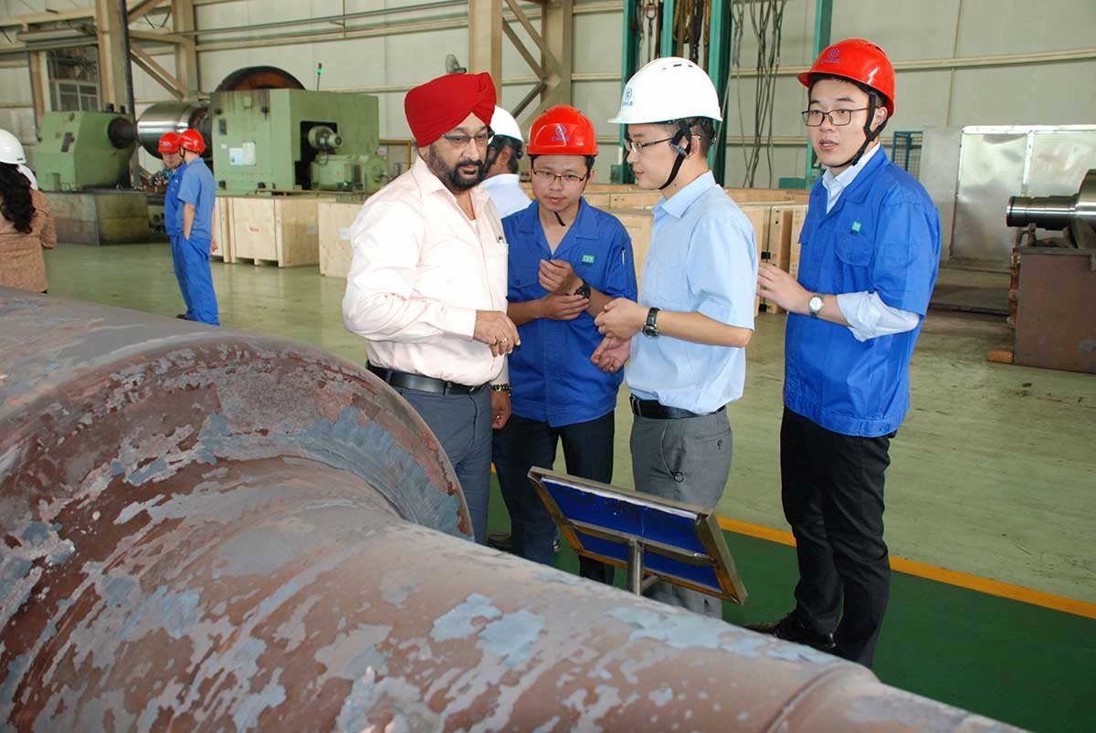
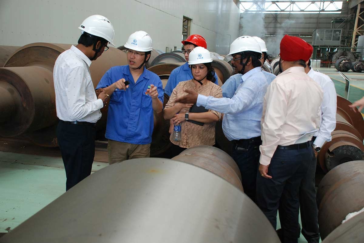
On 5th September, TATA STEEL INDIA delegation visited BAOSTEEL ROLL in Changzhou.
This is the first time in 10 years that TATA INDIA dispatch such a comprehensive delegation consists of 7 people who represent procurement, engineering, manufacturing, QC to take an on-site survey in BAOSTEEL ROLL.
The visiting is just before finalizing the annual contract of FY20. The delegation gives high appraisal of BAOSTEEL ROLL’s on-site management, technical capability, QC management, especially to the customized technical service. The delegation shows great interest on the new technology, the self-developed low frequency static induction hardening technology applied on the BUR project and further discussed about the hot strip mill BUR.
According to information, TATA STEEL plans several large capital merge project in India which aims at consolidating its leading position in steel industry.
The visiting helps further expanding and improving the business cooperation of both sides.